|
General Amperage Table | Insulation melting point amps | Low Voltage Types | Coaxial Cable | Speaker Wire
Conductor size is based one or more of the following considerations:
Current carrying capacity [inducing a rise in wire temperature, in high-voltage lines], Short circuit current, or Voltage drop [long low voltage lines].
Current carrying capacity varies depending on the type of insulation, current and use.
American wire gage every 6 gauge decrease gives a doubling of the wire diameter, and every 3 gauge decrease doubles the wire cross sectional area.
The wire size is dependent on amperage not voltage. The NEC code is for household AC power wiring, the others are generally for DC, but they should be about the same.
Conductor
Size (AWG) | Maximum Amperage | Diameter (in) | Resis-
tance
ohm/
1000' * |
NEC prem-
ises † | NEC General ‡ | ARRL2 | TFE insulated3 | Chassis wiring1 | Power Trans-
mission 1 |
stranded | Solid |
Bun-
dled 140°F insl. | Single 194°F insl. | Bun-
dled | Single | Bun-
dled | Single |
| 0000 4/0 | | 195 | 405 | | | 380 | | 302 | | | 0.46 | 0.05 |
| 00 2/0 | 200 | 145 | 300 | | | 87 | 169 | 283 | 190 | | 0.36 | 0.08 |
| 0 | | 110 | 220 | | | 75 | 147 | 245 | 150 | 0.38 | 0.32 | 0.1 |
| 1 | 150 | 95 | 190 | | | | | 211 | 119 | 0.33 | 0.29 | 0.13 |
| 2 | | 85 | 165 | | | 50 | 108 | 181 | 94 | 0.3 | 0.26 | 0.16 |
| 4 | 100 | 70 | 140 | | | 40 | 81 | 135 | 60 | 0.24 | 0.2 | 0.25 |
| 6 | 50 | 55 | 105 | | | 30 | 60 | 101 | 37 | 0.19 | 0.16 | 0.4 |
| 8 | 40 | 40 | 80 | | | 23 | 44 | 73 | 24 | 0.15 | 0.13 | 0.64 |
| 10 | 30 | 30 | 55 | | | 16 | 33 | 55 | 15 | 0.12 | 0.1 | 1.02 |
| 12 | 20 | 25 | 40 | 23 | 41 | 12 | 25 | 41 | 9.3 | 0.09 | 0.08 | 1.62 |
| 14 | 15 | 20 | 35 | 17 | 32 | 8 | 19 | 32 | 5.9 | 0.07 | 0.06 | 2.58 |
| 16 | | - | 24 | 13 | 22 | 6 | 13 | 22 | 3.7 | 0.06 | 0.05 | 4.08 |
| 18 | | - | 18 | 10 | 16 | 5 | 9.2 | 16 | 2.3 | 0.05 | 0.04 | 6.52 |
| 20 | | | | 7.5 | 11 | 3.7 | 6.5 | 11 | 1.5 | 0.04 | 0.03 | 10.36 |
| 22 | | | | 5 | 7 | 2.5 | 4.5 | 7 | 0.92 | | 0.03 | 16.46 |
| 24 | | | | | | 2 | 3.3 | 3.5 | 0.58 | | 0.02 | 25.67 |
| 30 | | | | | | 0.7 | 1.3 | 0.86 | 0.14 | | 0.01 | 103.2 |
AWG - American Wire Gauge
† Wire Size Specifications [NEC Table: UL486E]
Also National Fire Protection Association (NFPA 70)
- Cable sizing for premises wiring.
Wire must be two sizes larger (lower AWG) for Aluminum Wire.
‡ NEC Article 310 Conductors for General Wiring. (2008 Edition)
There two tables in this article one for bundled conductors and one for free air conductors. Each has three voltage ranges for insulation with different melting temperatures.
We used the low (60°C insulation bundled) and high (90°C insulation free air) values.
- Table 310.17 - Allowable Ampacities of Single-Insulated Conductors Rated 0 Through 2000 Volts in Free Air, Based on Ambient Air Temperature of 30°C (86°F)
- Table 310.16 - Bundled cables
Insulation temperature ratings:
- 60°C (140°F): Types TW, UF
- 75°C (167°F): Types RHW, THHW, THW, THWN, XHHW, ZW
- 90°C (194°F): Types TBS, SA, SIS, FEP, FEPB, MI, RHH, RHW-2, THHN, THHW, THW-2, THWN-2, USE-2, XHH, XHHW, XHHW-2, ZW-2
These tables also contain correction factors for ambient temperatures higher than 30°C ((86°F):
60°C (140°F): 0.6 (ie. max. amps is 60% the value above)
75°C (167°F): 0.4
1 - Handbook of Electronic Tables and Formulas for American Wire Gauge, H.W. Sams and Co., 6th edition (March 1986)
The Maximum Amps for Power Transmission uses the 700 circular mils per amp rule, which is very very conservative.
Chassis Wiring is meant for wiring in air, and not in a bundle.
2 - ARRL - Amateur Radio Relay League Handbook.
Based on max. wire temperature 100° C with ambient temperature 57° F
* Stranded wire
3 - MIL-STD-975 replaced by the NASA Parts Selection List. (NPSL)
The suggested MAXIMUM fuse rating is no MORE than 50% of the maximum current load a wire can handle.
Extension Cords
The NEC sets limits on the amount of current that cords are permitted to carry. This is for safety, to prevent overheating the cord. The limits for common cords are given under NEC premises in the chart above.
See the Extension Cord Page for size and length specifications to avoid excessive voltage drop.
Jump Starting Cables
Although most car battery ratings in Cold Cranking Amps (CCA) are from 540-880 CCA, a jump start cable only needs to support 85-150 Amps.
See Jump Starting
|
Allowable Amperage Of Current Carrying Conductors
Under 50V As Suggested By The American Boat And Yacht Council (ABYC)
Allowable amperage of single conductors rated 105C - Outside / Inside of Engine Space
| AWG | Amps |
| Outside | Inside |
| 18 |
20 |
17 |
| 16 |
25 |
21 |
| 14 |
35 |
30 |
| 12 |
45 |
38 |
| 10 |
60 |
51 |
| 8 |
80 |
68 |
| 6 |
120 |
102 |
| 4 |
160 |
136 |
| 2 |
210 |
178 |
| 1 |
245 |
208 |
| 1/0 | 285 |
242 |
| 2/0 | 330 |
280 |
| 4/0 | 445 |
378 |
Source: Marine Wire Size - Marine Wire and Cable
American specs covering automotive wire are SAE J 1127 and J-1128, specifying resistance to heat and mechanical damage.
There are two basic types of insulation covered in these specs:
Polyvinyl Chloride, (PVC ), and Cross-linked Polyethylene, (XPE).
GPT, TWP, and HDT wire insulations are all Polyvinyl Chloride (PVC) based insulations used in cooler parts of the car with a 185°F/85°C rating.
SXL, GXL, and TXL (thin, medium, and thick insulation) wire are Cross-linked Polyethylene, (XLP) and used under the hood. They have a 257°F/125°C temperature rating.
Maximum current capacity depends on the melting temperature of the insulation.
TFE - Tetrafluorethylene.
Teflon TFE- Teflon a DuPont trademark.
PTFE - Polytetrafluoroethylene
ETFE - Ethylene Tetrafluoroethylene
| | Insulation Type |
Conductor
Size | Polyethylene
Neoprene
Polyurethane
Polyvinylchloride
(Semi-Rigid) | Poly-
propylene
Polyethylene
(High Density) | Polyvinyl-
chloride
PVC
(Irradiated)
Nylon | Polyethylene
(Crosslinked)
Thermoplastic
Elastomer | Kapton
Teflon
Silicone |
Max
Temp | 80° C | 90° | 105° | 125° | 200° |
| 176° F | 194° | 221° | 257° | 392° |
| AWG | Maximum Current - Amps
|
| 2 | 170 | 180 | 200 | 225 | 240 |
| 4 | 125 | 135 | 145 | 170 | 180 |
| 6 | 95 | 100 | 105 | 125 | 135 |
| 8 | 65 | 70 | 75 | 90 | 100 |
| 10 | 47 | 55 | 58 | 70 | 75 |
| 12 | 36 | 40 | 45 | 50 | 55 |
| 14 | 27 | 30 | 33 | 40 | 45 |
| 16 | 19 | 22 | 24 | 26 | 32 |
| 18 | 15 | 17 | 18 | 20 | 24 |
| 20 | 10 | 12 | 13 | 14 | 17 |
| 22 | 8 | 9 | 10 | 11 | 13 |
| 24 | 6 | 7 | 7 | 8 | 10 |
| 26 | 4 | 5 | 5 | 6 | 7 |
| 28 | 3 | 4 | 4 | 5 | 6 |
| 30 | 2 | 3 | 3 | 3 | 4 |
Source: Alpha Wire
High ambient temperature increases the chance of insulation meltdown, so max. amperage is reduced.
De-rating for high temperature:
Copper Wire Correction
| Temperature | 40°C | 45°C | 50°C | 55°C | 60°C | 70°C |
| 104°F | 113°F | 122°F | 131°F | 140°F | 158°F |
| DerateAmpacity | 0.88 | 0.82 | 0.75 | 0.67 | 0.58 | 0.33 |
Low Voltage Cable Types
MP - Multipurpose cable
CM - Communications Cable
PLTC - Power-limited tray cable
Article 725, Class 2
   725-38(b)1      CL2X    Class 2 cable, limited use
   725-38(b)1      CL2     Class 2 cable
   725-38(b)2      CL2R    Class 2 riser cable
   725-38(b)3      CL2P    Class 2 plenum cable

Class 2, Class 3 - Remote-control, signaling, and power-limited cables
Class 1 - Power and lighting cables
FPL - Power-limited fire protective signaling cables
Maximum Power Supply size for Class 2 Circuits is 100 VA
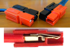
Anderson Powerpole Connectors:
The Anderson Power Multipole Connectors are color coded with mechanical voltage keys to prevent mismatching power supplies and electrical outlets. Flat wiping contacts clean the contact surface during disconnection and allow for minimal contact resistance at high current. The Multipole Connectors are genderless housings that are capable of 10,000 mating cycles.
The 30-amp Anderson Powerpole connector is being adopted by ARES & RACES groups nationwide.
Products:
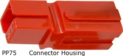
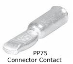
  Housing  Contact
PP15/30/45: 30A, 600V AWG #16 to #12 -The standard for amateur radio
PP15/30/45: 45A, 600V AWG #14 to #10
PP75:       75A, 600V AWG #16 to #6
    You order contacts separately #6, #8, #10, #10/12
Standard Powerpole® Family at andersonpower.com
Anderson Power Poles, Connectors & Housings | Powerwerx
Powerpoles and Related Hardware | qsradio.com
Anderson Power Connectors at Solar-Electric
Anderson Power Products | Anderson Power Products Distributor : Mouser.com
Anderson Powperpole IDEAS at buck0
Anderson Powerpole Instructions | wb3w.net
Notes at San Antonio Hams
DC Power distribution Pannels:
eHam.net Reviews - DC Power Supply Distribution Panels
RIGrunner 4012 West Mountain Radio
See:
Coaxial Cable
Power Requirements of appliances
American Wire Gauge (AWG) and Current Limits
DC connectors - Wikipedia
Copper wire
Car Audio Wiring
Wire Size Chart at OmenTrance.com
AWG Cable Description
Glossary
2002 NEC
Electrical Code Basics
Copper Wire characteristics
Wire Gauge and Current Limits at Power Stream
Amateur Radio Wiring at k0bg.com
Copper Wire Figures ata EPanorama.net
last updated 16 Mar 2006
|
 Home - Garden